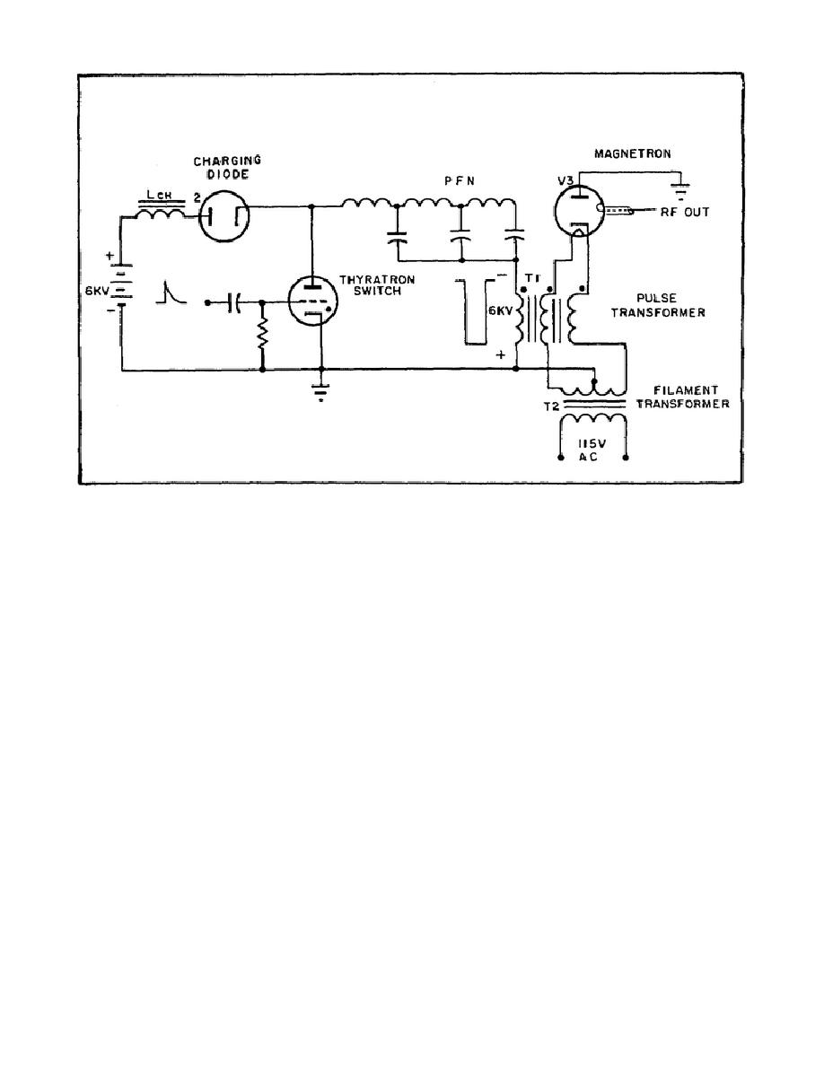
Figure 63. High-Level Modulator With Pulse
Transformer and Magnetron Load.
2.
Pulse transformer windings.
a. The dots you see on the transformer windings (T1) in Figure 63
indicate points having the same polarity.
Thus, if one dot represents a
negative polarity, then all the dots are negative.
Notice the secondary,
connected to the magnetron filament. The secondary is bifilar, that is, the
two secondary windings are wound side by side on the core. Wound in this
manner, the secondary has exactly the same voltage induced into each
winding.
b. Perhaps you are wondering, why use a bifilar secondary when one will
do the job? Look at Figure 64 for the answer. Part A of Figure 64 shows a
pulse transformer with just one secondary winding.
Notice that with a
transformer step-up ratio of 1:2, the negative voltage on the magnetron
cathode is 12KV.
This means that the secondary of the magnetron filament
transformer, T2, is a negative 12KV with respect to the primary.
To
withstand this high voltage, the filament transformer must be heavily
insulated, thereby making it bulky and expensive. Another disadvantage of
this circuit in Part A is that there is uneven magnetron cathode emission,
because there is a difference of potential across the magnetron cathode.
One side of the cathode is at minus 12KV; the other side is at a lower
potential because of the drop across the cathode itself.
80


 Previous Page
