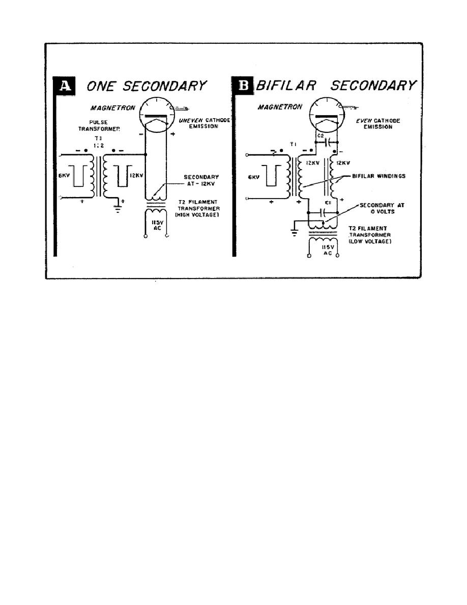
Figure 64.
The Pulse Transformer With Bifilar Windings.
c. Compare this to the pulse transformer with a bifilar secondary shown
in Part B of Figure 64.
Notice that the secondary of the filament
transformer is center-tapped and grounded.
The high-voltage DC potential
across the filament transformer secondary is now zero, with respect to
ground, because both ends of the secondary are at the same potential.
Therefore, a conventional low-voltage filament transformer can be used.
Note, too, that both ends of the magnetron cathode are at the same
potential. Capacitors, C1 and C2, ensure that there is no high difference
of potential between the two secondary bifilar windings.
This prevents
uneven cathode emission and thereby stabilizes magnetron operation.
3.
a. In some radar installations, the antenna is located at some distance
from the transmitter. This means that a long coaxial line or waveguide must
be used to connect the magnetron to the antenna. But long RF lines tend to
make magnetron operation unstable. Therefore, they should not be used.
b. Figure 65 shows a solution to this problem of long lines: separation
of modulator and magnetron. The magnetron is at the antenna to keep the RF
transmission line as short as possible.
A special coaxial pulse cable
carries the
81


 Previous Page
