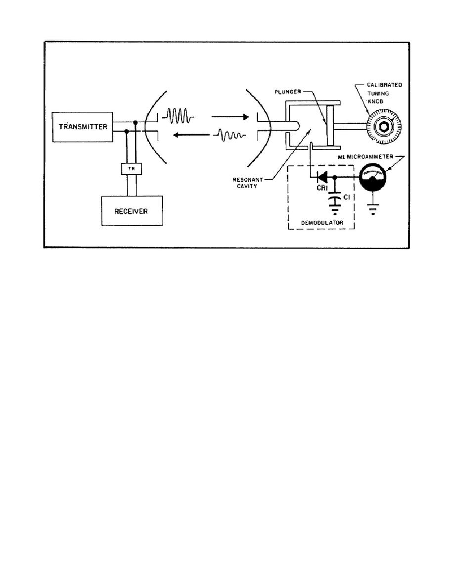
Figure 82. Echo Box as Used to Check
Radar Set Performance.
b. The echo box in Figure 82 has more than just a resonant cavity. In
addition to the cavity, it contains a demodulator circuit, a microammeter,
and a knob with a calibrated dial.
c. The demodulator circuit consists of crystal diode CR1 and capacitor
C1. The crystal diode rectifies the RF energy. The capacitor shunts the RF
component to ground and filters the pulsating DC.
Therefore, when the
cavity is excited, DC flows though microammeter M1.
d. The resonant cavity is plunger-tuned with a knob that has a
calibrated dial.
The dial indicates the frequency to which the cavity is
tuned.
26. How you use the echo box.
a. Using the echo box, you can determine if the radar set is operating
at the correct frequency. Here's how:
(1) Adjust the tuning dial until the meter gives a maximum reading.
You will get a maximum reading only when the echo box is tuned to the radar
frequency.
(2) Read the frequency indicated by the calibrated dial.
The dial
setting indicates the radar transmitter frequency.
b. So, you see how important the echo box is in determining if the
radar transmitter is operating at its assigned frequency.
118


 Previous Page
