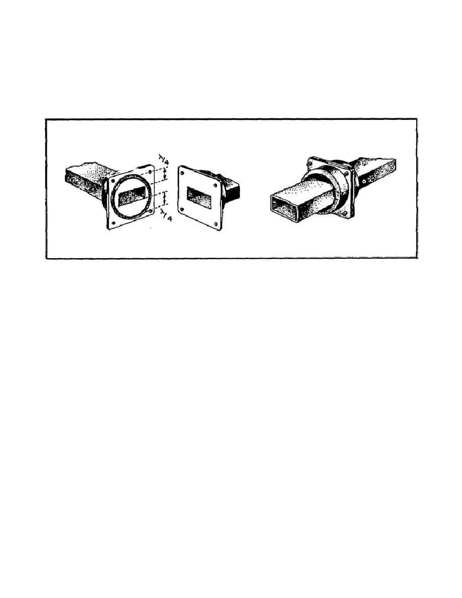
22. Fixed rectangular joints.
a. Waveguide systems usually have several sections that can be taken
apart for inspection, cleaning, and easy replacement. Systems with several
sections also allow for heat expansion.
To minimize reflections, two
sections are usually coupled with a joint similar to the rotating choke
joint. Figure 119 shows a typical connection.
Figure 119.
Rectangular Waveguide Joint.
b. As with rotating joints, one section is fitted with a choke plate
and the other section with a flange.
The operation of this fixed choke
joint is exactly the same as that of the rotating joint.
There is one
difference, however, between circular and rectangular waveguide joints. In
circular waveguide, the choke groove is a quarter wavelength between all
points of the inner wall of the guide.
With rectangular waveguide, the
groove is a quarter wavelength away from the inner walls at only two points
as shown in Figure 119.
These two points, however, are located where the
electric field is maximum, so there is only a slight loss of energy at the
other points.
c. When you connect two sections of waveguide, it is important that you
put the correct ends together. Otherwise, serious reflections will occur,
causing a loss of power. The right and wrong ways of connecting sections
are shown in Figure 120.
174


 Previous Page
