MM0474
entire bridge is floating with respect to DC ground.
This circuit
configuration provides a virtual 10 kHz ground at, the RF input point to the
balanced thermistor mount.
j. Compensation and Metering Bridge Circuit.
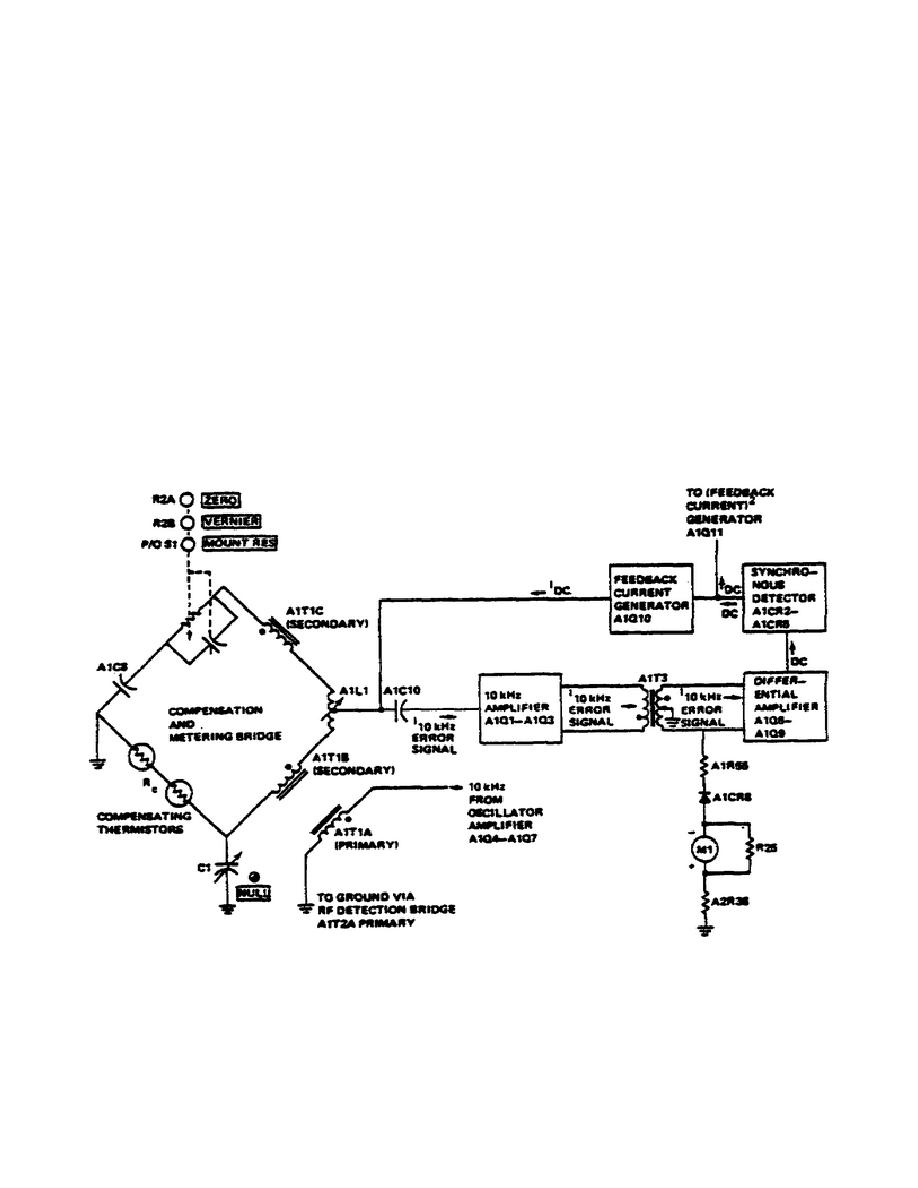
(1) A simplified schematic diagram of the compensation and metering
bridge circuit is shown in Figure 10. Operation of the metering bridge circuit
is similar to the RF detection bridge circuit. It uses the same principle of
self-balancing through a closed loop (metering loop). The major difference is
that DC rather than 10 kHz power is used to re-balance the loop. The resistant
balance point is adjusted by the ZERO and VERNIER controls which constitute one
arm of the bridge. The MOUNT RES switch, which is mechanically linked to both
the RF bridge and metering bridge, changes metering bridge reference resistance
from 100 to 200 ohms. When the MOUNT RES switch is in the 200 ohm or 200 ohm
BAL position some of the feedback current is shunted to ground through R1.
This maintains the I2R function constant when mount resistance is changed from
100 to 200 ohms.
The switch also adds the necessary reactance for each
position.
Figure 10.
Compensation and Metering Bridge.
26


 Previous Page
