MM0474
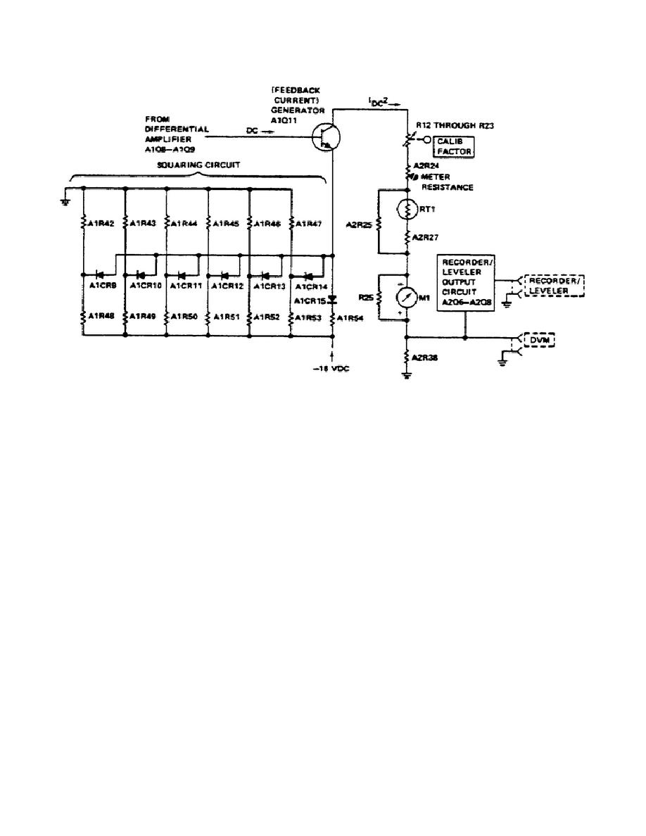
Figure 14.
Meter Circuit.
loop circuit is self balancing and uses DC feedback to rebalance the closed
loop.
Resistive balance is set by R2A and R2B ZERO controls, front panel
adjustments which are in one leg of the Metering Bridge. DC offset voltage on
the base of A1Q8 determines the balance point of the closed loop. A1R37, ZERO
CARRYOVER, sets the amount of this offset for about +50 millivolts.
p. DC Substitution.
A simplified schematic diagram of the DC Substitution and Calibration
circuit is shown in Figure 15. An accurately determined DC current, IDC, is
supplied to the DC CALIBRATION terminals on the rear panel and adjusted to
allow the RF detection bridge to precisely duplicate the RF power measurement
reading.
Calculation of DC power from the substituted DC current gives an
accurate measure of the unknown RF microwave power.
q. Regulated Power Supply.
(1) A simplified schematic diagram of the power supply is shown in
Figure 16. The power supply operates from either a 115 or
31


 Previous Page
