MM0474
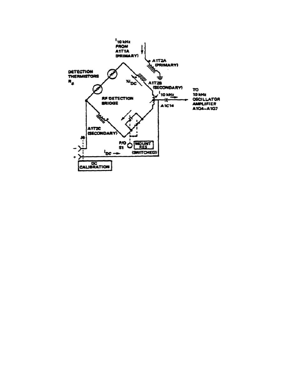
Figure 15.
DC Calibration and Substitution.
230 volt, 50 to 400 Hz AC source or from an optional 24 volt, 30 mA
rechargeable battery. Three voltages and two current outputs are provided by
the power supply.
Regulated voltages of -18, +1.3, and unregulated -25 VDC
operate the power meter circuits. The current outputs are used for maintaining
a trickle battery charge for recharging the battery.
(2) The -18 VDC is regulated by a conventional series regulator, A2Q1
through A2Q5.
The unregulated -25 VDC is developed across A2CR1 and A2CR4.
The +1.3 VDC is taken across the series diodes, A2CR6 and A2CR7. The -18 VDC
Supply is adjusted by A2R36.
r. Power Switch.
A simplified schematic diagram of the power switch arrangement is shown
in Figure 16. The POWER switch has five positions: LINE OFF, LINE ON, BATTERY
ON, BATTERY TEST, and BATTERY CHARGE. In the line ON position the instrument
operates from the conventional line voltage.
If a rechargeable battery has
been installed, a trickle charge is supplied to the battery. In the BATTERY ON
position, instrument operation is dependent on the battery.
In the BATTERY
CHARGE position, -25 volts is connected to the battery for recharging. In the
BATTERY TEST position, battery voltage can be measured on the 0-3 mW scale.
Battery voltage
32


 Previous Page
