MM0474
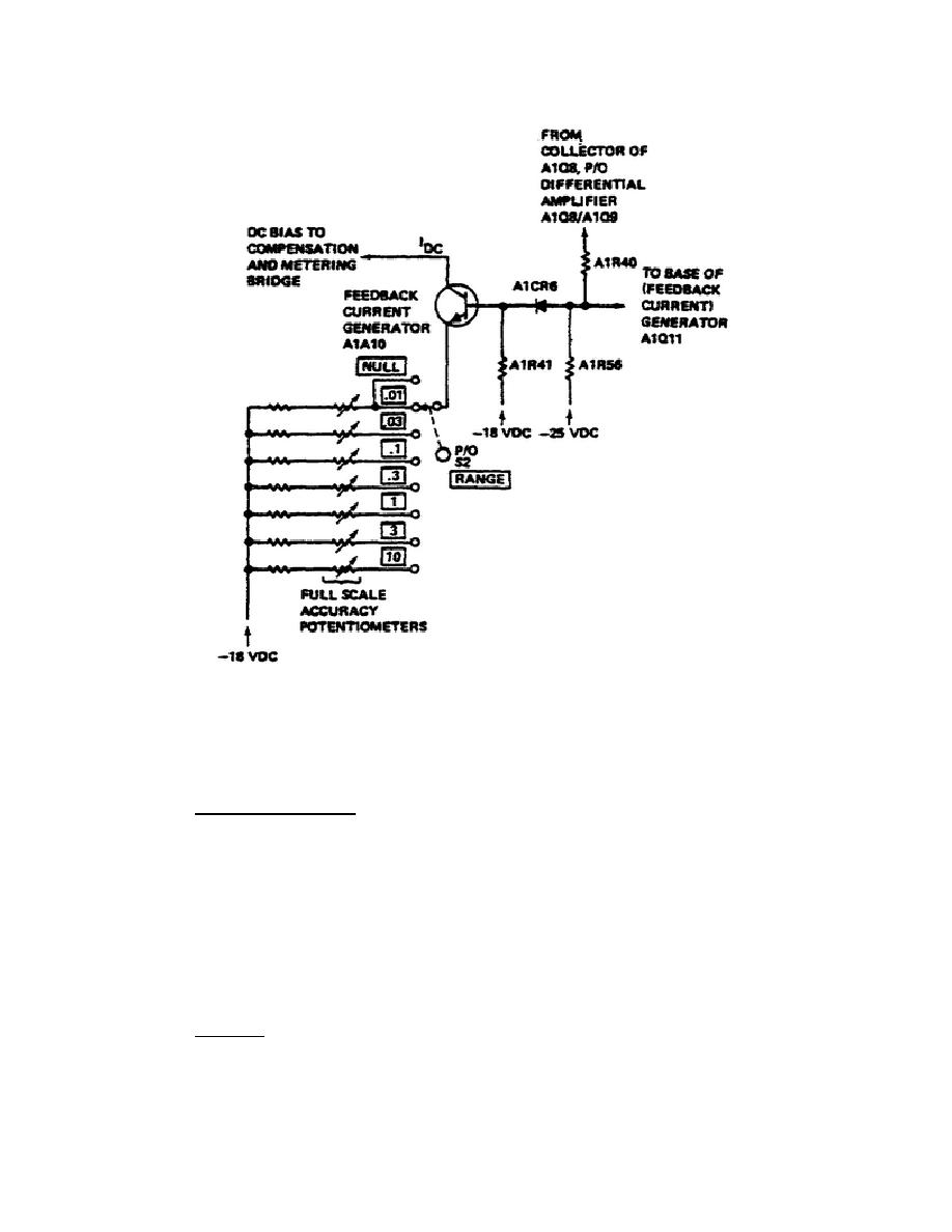
Figure 13.
Feedback Current Generator.
A2Q8.
A corresponding change in A2Q8 collector current occurs and the
RECORDER/LEVELER voltage across A2R41 automatically adjusts to maintain the
same magnitude as the DVM reference voltage.
(2) Squaring Circuit.
A simplified schematic diagram of the squaring
circuit is shown in Figure 14. The squaring circuit includes diodes A1CR9-14
and resistors A1R42-54. Temperature compensation for the squaring circuit is
provided by A1CR15.
(3) The design of the squaring circuit is such that individual diodes
are normally reverse-biased.
The diodes are biased so that they conduct one
after another at discrete values of emitter voltage. This causes the emitter
resistance to be proportionately greater for larger currents.
Thus, the
collector current of A1Q11 is made to approximate a square law function, and
the meter indicates power on a linear scale.
(4) Zeroing. The resistance of the Metering Bridge is never balanced.
A small amount of unbalance must exist to provide error signal for the
operation of the feedback loop. The Metering Bridge
30


 Previous Page
