MM0474
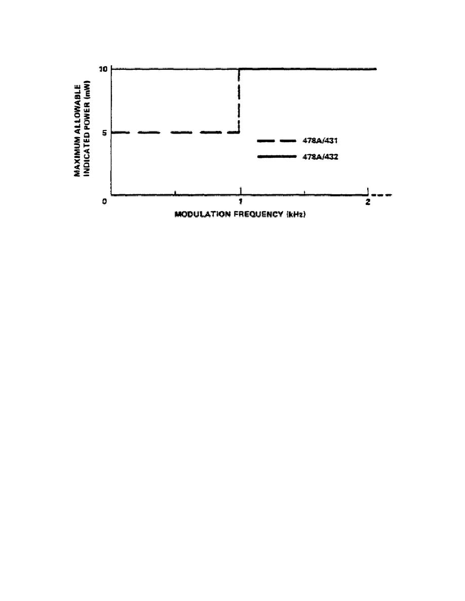
Figure 29.
Maximum power meter reading versus square
and sine-wave frequency.
g. In the discussions above, the primary consideration is maximum-power or
energy.
However, for modulation frequencies less than 100 Hz, the low
repetition frequency itself causes errors in indicated power. These errors may
be as large as 2% regardless of range or of reading.
h. Drift Precautions.
Thermistors are inherently temperature sensitive
devices. A cold thermistor mount connected to a warm piece of equipment, or
vice-versa, produces rapid drift. For minimum drift on sensitive ranges, make
sure that the mount and the equipment connected to it are at nearly the same
temperature before making a measurement.
(1) Two matched series thermistors are mounted on a common thermal
conduction block, represented by the shaded rectangle in Figure 30, one pair,
marked D for detection, is mounted between the end of a coaxial cable and a
cylindrical cavity. These thermistors are exposed to incoming RF power which
heats them, lowering their resistances.
The other pair marked C for
compensation and situated immediately outside the cavity is completely shielded
from RF. With 478A attached to the 431 Power Meter, the detection thermistors
are part of its metering circuit.
With the 478A attached to the 432 Power
Meter the detection thermistors are part of the RF bridge and the compensation
thermistors are part of the compensation bridge.
Since the two pairs of
thermistors share the same thermal environment, any change in temperature which
affects the rf bridge simultaneously affects the metering bridge, thereby
allowing the power meter circuit to compensate for changes in temperature, and
thus to minimize drift.
64


 Previous Page
