MM0474
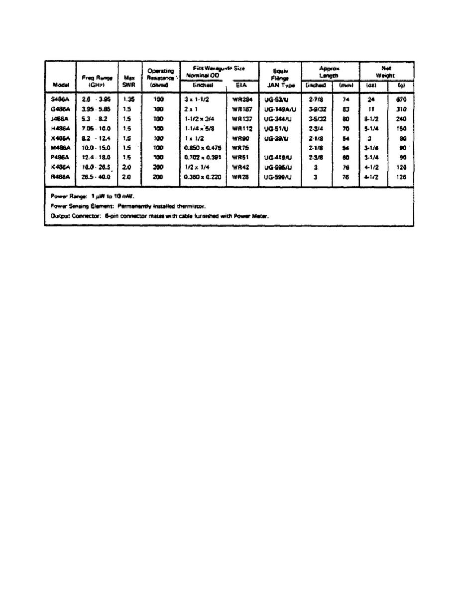
Table 6.
Specifications.
b. Precautions.
Mechanical Shock. DO NOT DROP OR SUBJECT TO SEVERE MECHANICAL SHOCK.
SHOCK MAY DESTROY THE MATCH BETWEEN THERMISTORS AND INCREASE SUSCEPTIBILITY TO
DRIFT.
CAUTION
Before connecting a 200 ohm thermistor mount (K or R486A) to a power meter, set
MOUNT RES switch to 200 ohm position. CONNECTING A 200 OHM MOUNT TO A POWER
METER SET FOR A 100-OHM MOUNT CAN RESULT IN THERMISTOR DAMAGE.
(3) Under normal operation, the total power supplied to heat thermistor
pair D (see Figure 30) consists of: 1) RF signal, 2) 10 kHz bias and 3) heat
from the environment.
The total power supplied to heat thermistor pair C
consists of: 1) DC bias, 2) an equal amount of 10 kHz bias, and 3) heat from
the environment. As D and C are matched thermally, the total amounts of heat
applied to reduce their series resistances equally must be equal.
5.
MODEL 486A THERMISTOR MOUNT.
a. Introduction.
(1) Model 486A Thermistor Mounts are designed for use with Model 431 and
432 Power Meters in the measurement of microwave power from 1 W to 10 mW in the
range from 2.6 to 40.0 GHz. Design of power meter and thermistor mount is such
that the measurement system is temperature-compensated. This feature permits
microwave power measurements that are relatively free of the drift in meter
indication that otherwise occurs with changes in ambient temperature. Table 6
lists the 486 series and their specifications.
66


 Previous Page
