MM0474
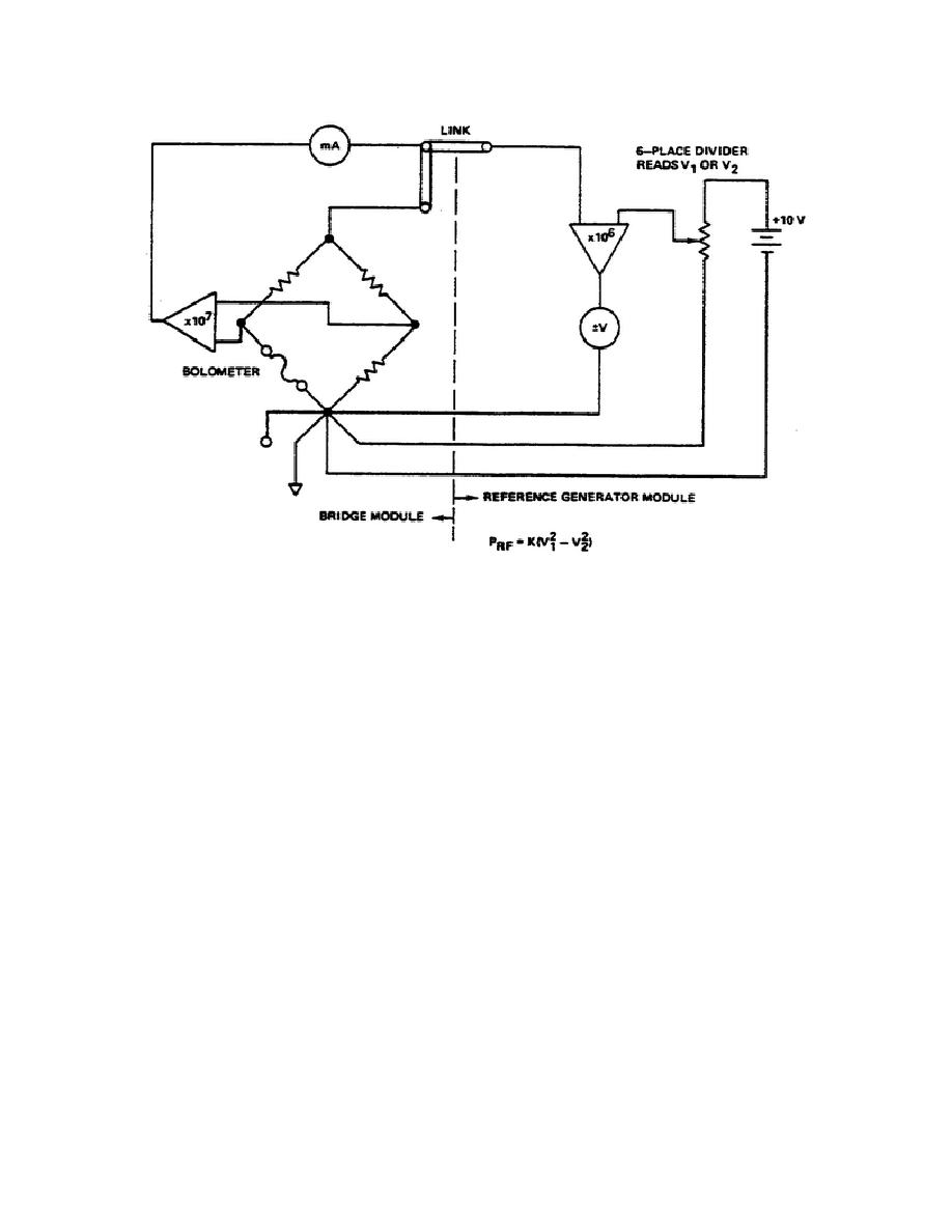
Figure 9.
Basic measurement system.
The operational amplifier marked X107 senses the bridge
straightforward.
balance and adjusts the bridge current up or down to maintain a null at the
amplifier input terminals.
As RF power is applied to the bolometer its
resistance will increase (if the element is a barretter). The bridge circuit
detects this and reduces the bridge current to maintain the bolometer element
resistance constant. This reduction in DC power is calculated and is ideally
equal to the RF power dissipated in the bolometer element. (In practice it is
not exactly equal to the RF power because of DC-RF substitution errors.)
(2) In Figure 9, the reference generator is connected as a voltmeter
with the function switch in the NULL position. The amplifier marked X106 (G700
board) is acting as a null detector, indicating when the divider dials are set
to the voltage appearing at the top of the bridge. This voltage .is measured
first with the RF off (V1) and then with the RF on (V2). The RF power as a
function of V1 and V2 is given by the expression at the bottom of the figure.
The value of K depends upon the operating resistance of the bolometer element
used. The value of K is given by:
115


 Previous Page
