MM0474
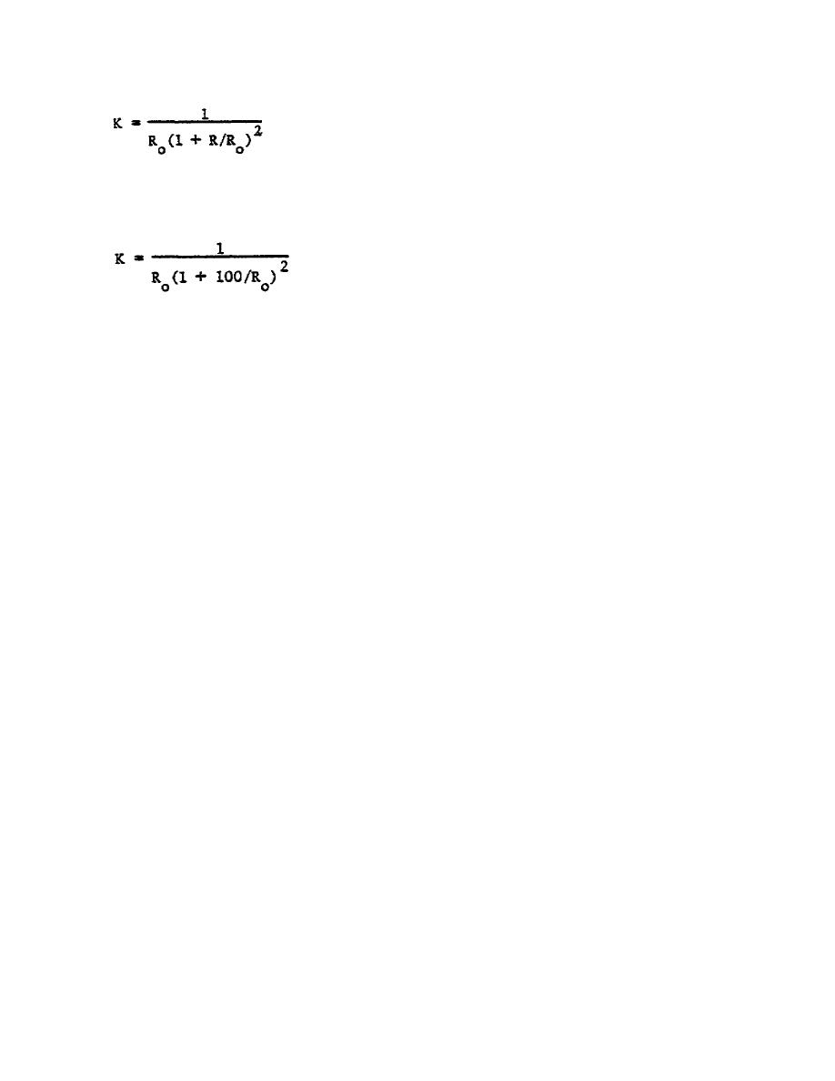
where Ro is the element operating resistance, and R is the value of each of the
two "top" arms of the bridge. In this bridge, R is equal to 100 ohms, so that
the expression for K becomes:
(3) The divider dials are direct reading to nominally 0.01%, but using
this method does not result in the most accurate power measurement. This is
particularly true at low RF power levels where V1 and V2 are nearly equal in
value. The dotted line in Figure 10 reveals this. Note that both curves in
this figure are the result of using a voltmeter with the accuracy stated in
Table 1 under ACCURACY.
c. Precision Power Meter.
(1) Figure 6 indicates that an external voltmeter is required for this
procedure.
This voltmeter should be the most accurate available.
The
following section on error analysis gives an expression for the error in the
measurement due to the uncertainties in the voltmeter. The V-REM-V switch is
shown in the figure. The bridge circuit remains the same, but the reference
generator operational amplifier has been connected as a unity gain follower.
This is done by placing the function switch in the RVG position. The follower
isolates the divider from leading errors.
(2) The basic power measurement equation may be rewritten giving the
expression of Figure 6. Here V1 is the DC bias bridge voltage, and V is the
change in the voltage when RF is applied to the bolometer mount.
If the
divider is set to the voltage V1, then, when the RF is turned on, a voltmeter
connected between the bridge and the divider output will indicate the change in
voltage V, directly. K is the same as given in Paragraph 7b.
(3) An examination of Figure 6 will show chat when the V-REM-V switch
When in the V
is in the V position shown, the voltmeter can read V1.
position, the external voltmeter may be used as a mill detector for setting the
divider and then also for reading V.
(The REM position is for a possible
future circuit addition and is not active in these units.)
(4) As Figure 10 shows, the error in making the DC substituted power
measurement by this method is reduced substantially.
The discontinuities in
the curve are due to range changes in the external voltmeter.
116


 Previous Page
