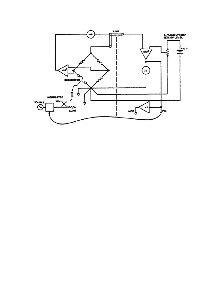
MM0474
Figure 7.
Precision power stabilizer.
b. Operating Procedure-Power Stabilizer.
(1) The initial steps of para. 4a should be followed first.
In
addition, place the reference generator function switch in the STAB position
and connect the modulator to the appropriate front panel terminal.
(2) With the bridge on, and the RF off, note the bridge voltage and set
the reference generator divider dials to that voltage or slightly higher. This
may be done with an external voltmeter or by using the reference generator as a
voltmeter as outlined in para. 4e. If the latter technique has been employed,
place the generator function switch back in the STAB position after determining
the voltage.
Setting the stabilizer operating point in this manner, before
turning the RF power on, insures that the modulator will be set to nearly its
maximum attenuation. This prevents possible excessive power from reaching the
leveling bolometer mount or the load.
(3) Turn on the RF power and reduce the voltage setting of the divider
dials to the desired operating point.
A corresponding reduction in bridge
current should be noted. The maximum RF power available to the leveling mount
should be such that setting the divider dials to zero does not result in a
reduction of bridge current to zero.
In other words, when the leveling
modulator is set to its minimum attenuation, the RF power arriving at the
leveling mount should not exceed its DC
112


 Previous Page
