MM0474
(5) The bolometer mount may now be attached to the bridge and the
instrument turned on.
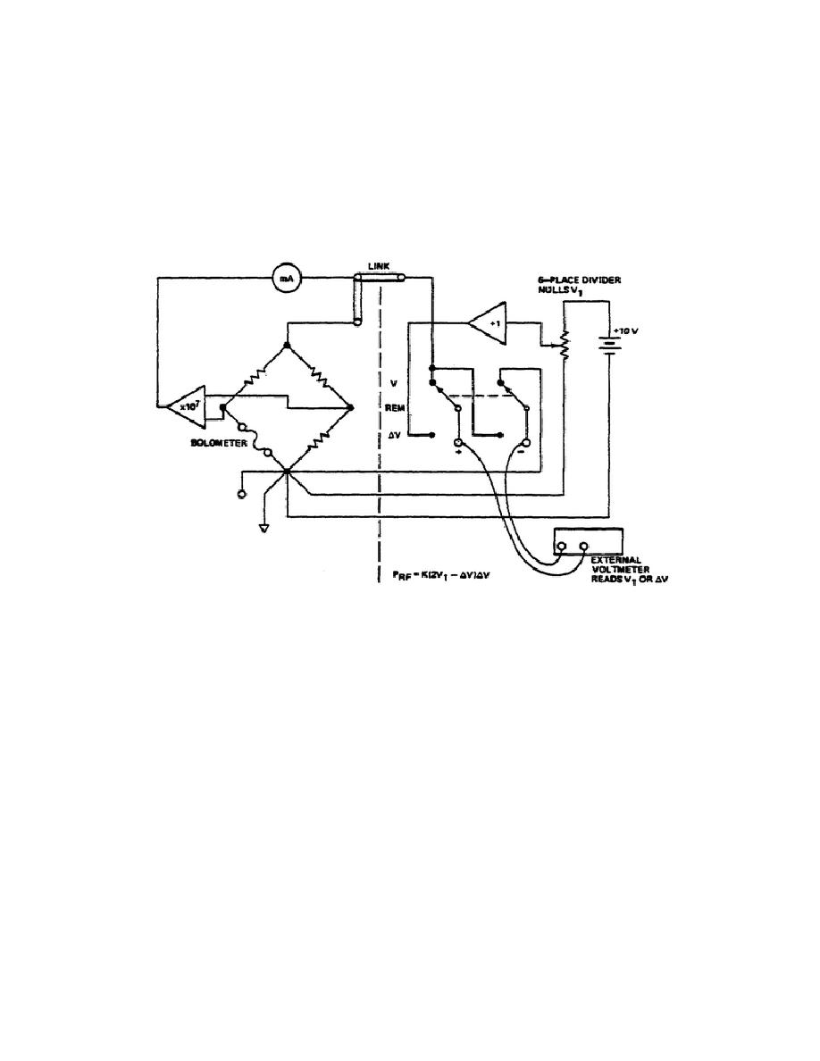
b. Precision Power Measurement (Figure 6). This measurement requires the
use of an external voltmeter.
The accuracy of this voltmeter should be as
accurate as possible, since its error contributes directly to the overall
measurement error. The voltmeter should be connected to binding posts 21 and
22 located on the lower part of the reference generator.
Figure 6.
Precision power measurement system.
c. Measurement Procedure.
(1) After the instructions of para 4a have been followed, turn on the
bridge and allow a 15 minute warm up period.
(2) The bolometer mount should be attached to the RF power source, but
with the RF power off.
(3) Place the reference generator function switch in the NULL position
and the V-REM-V switch at V. Adjust the divider dials to zero.
109


 Previous Page
