
MM0474
mount. The proper position may be determined by noting the connections to the
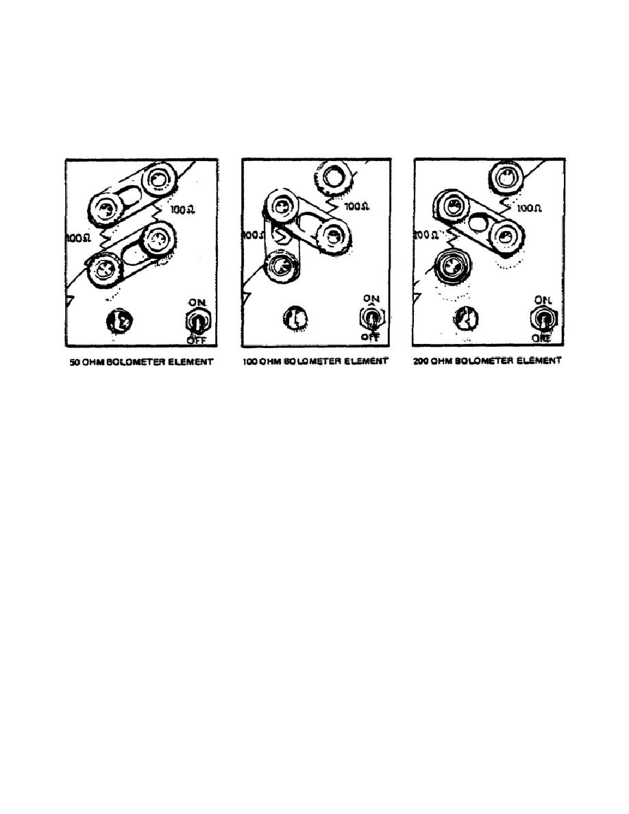
100 ohm resistors as indicated by the front panel or by referring to Figure 4,
which show the link positions for various operating resistances. An external
resistance standard may be connected if the desired operating resistance cannot
be achieved with the internal resistors.
Figure 4.
Front panel link positions.
Indicates the total bridge current 3%.
(11) BRIDGE CURRENT METER.
Not
used for power measurement.
(12), (13)
CURRENT SAMPLING TERMINALS. If it is desired to measure accurately
the bridge current, an external ammeter may be inserted at this point. If it
takes the form of a current sampling resistor, the total voltage between
terminals 13 and 4 should not exceed LO volts to ensure proper bridge
balancing.
(14) REFERENCE GENERATOR INPUT TERMINAL.
This terminal is normally
connected by a link to the top of the bolometer bridge, terminal 13, as
in the NULL mode, it is the positive input. The negative input is accomplished
through the rear cable.
(15) OUTPUT VOLTAGE METER.
In the reference voltage generator mode,
(RVG), this meter displays the voltage to which the decade divider dials are
set. In the voltmeter (NULL) mode, the meter indicates the output of the null
detector amplifier.
In the stabilizer (STAB) mode, the meter monitors the
output voltage of the leveling amplifier and may be used to help determine when
the stabilizer is operational, particularly when used with PIN diode
106

 Previous Page
