
MM0474
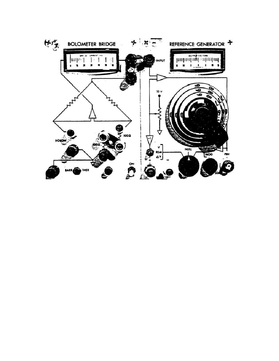
Figure 3.
Front panel controls, connectors, and indicators.
(3) BARRETTER/THERMISTOR SWITCH.
Selects amplifier feedback polarity
and response shaping networks in both bridge and generator for either a
positive or negative temperature coefficient bolometer elements (S601).
(4) COMMON REFERENCE TERMINAL.
Common ground return point for all
bridge and reference generator circuits.
(5) BOLOMETER MOUNT NEGATIVE TERMINAL.
(6) BOLOMETER MOUNT POSITIVE TERMINAL.
The connecting leads to the
bolometer mount should be as short as possible.
For the most accurate
measurement lead resistance should be measured and corrected for.
(7) THROUGH (10).
MOUNT RESISTANCE.
The position of the removable links on these
terminals determines the operating resistance of the bolometer
105

 Previous Page
