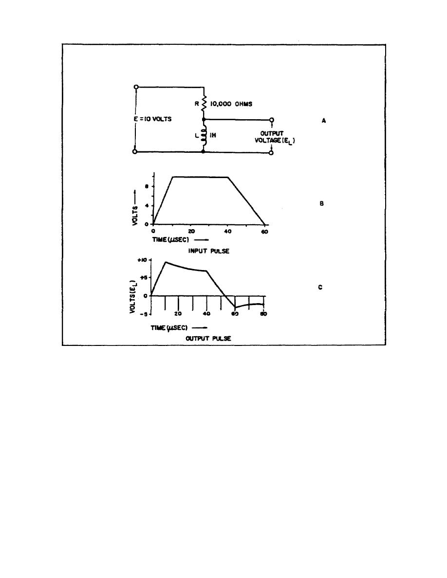
Figure 38. Input and output pulses for a long
timeconstant series RL circuit
26.
LONGTIME CONSTANT.
a. When the time constant is long compared to the pulse rise,
duration, and decay times, the voltage drop across the resistor is a
small fraction of the applied voltage. Most of the applied voltage
appears across the inductor, and the output waveform closely
resembles the input waveform.
b. The pulse in Figure 38B is applied to the highpass RL filter
in Figure 38A. The time constant is 100 usec. Since the pulse rise
time (10 usec) represents only 10 percent of 1 time constant, the
current and ER reach only a low value during this time. The output
voltage EL very closely follows the rise of the input pulse.
75


 Previous Page
