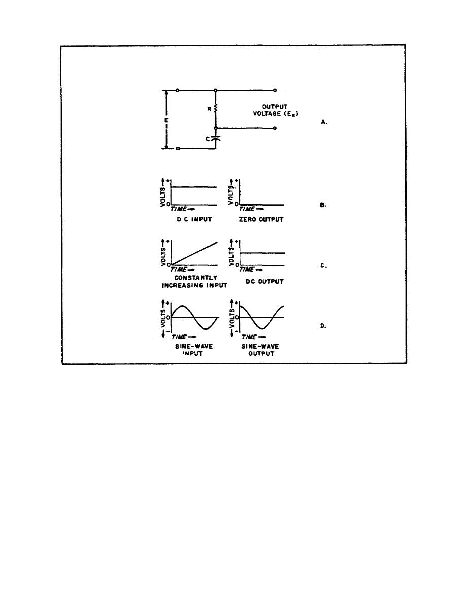
Figure 41. Differentiator circuit input and
output pulses
b. The DC voltage indicated in Figure 41B is applied to the RC
differentiator circuit of Figure 41A. After the circuit has reached
its steadystate condition, the rate of change in voltage is zero,
and the differentiated output is zero. The input voltage in Figure
41C has a constant, positive rate of increase. When this voltage is
applied to the differentiator circuit shown in Figure 41A, a constant
DC voltage is obtained at the output. The amplitude of the output
voltage depends on the input voltage rate of change and the time
constant of the circuit. The higher the voltage rate of change, the
greater the DC voltage output. The longer the RC time constant, the
greater the DC output.
81


 Previous Page
