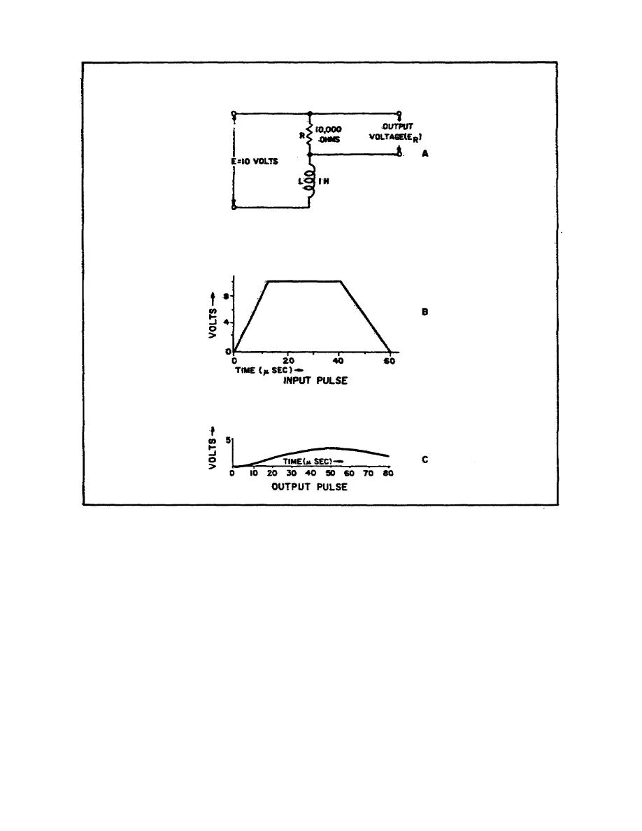
Figure 46. Integrator circuit input and
output pulses
b. In Figure 46C, it can be seen that, upon application of the
input pulse to the integrator, ER increases gradually in a positive
direction. This voltage rise across the resistor continues until the
applied pulse begins to decay. At that time, the output voltage
decays gradually until the next pulse is applied. Outputs of typical
input waveforms are shown in Figure 47. In each case, the output
voltage increases or decreases, and the amplitude is proportional to
the length of time that the pulse is applied or the length of time
between pulses.
88


 Previous Page
