the transistor from high surges of back voltage, which would occur if the
loudspeaker voice-coil winding should become disconnected. A small power
loss is accepted as the price for protecting the transistor.
c. Push-Pull Output Stage.
Where more power is required than a single-ended
amplifier can furnish, two transistors can be combined in a push-pull amplifier.
This type of amplifier has the combined advantages of greater output and the
ability to cancel out many of the distortion products created by the transistors.
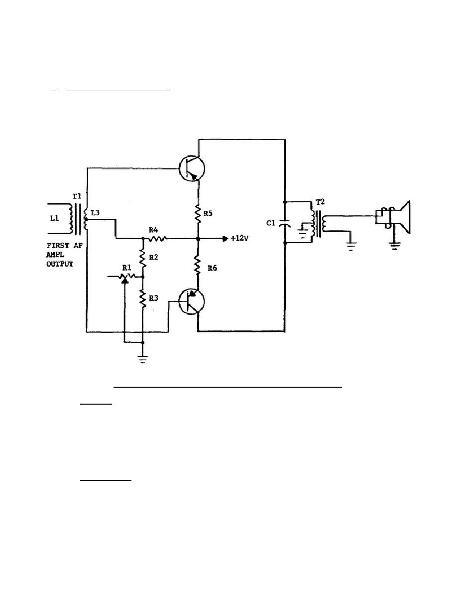
Figure 4-3 illustrates a class AB power amplifier employing two PNP high-power
transistors in a push-pull circuit.
Figure 4-3.
Push-pull transistor output amplifier.
(1) Biasing.
A common-emitter arrangement is used with +12 volts applied to
the two emitters through R5 and R6.
Resistors R1 through R4 form a
voltage divider to develop a bias voltage. The base of each transistor is
connected to its respective emitter circuit through one half of input
transformer T1 and resistor R4.
Both collectors are connected to ground
through one half of the T2 primary, the output coupling transformer that
drives the loudspeaker.
Resistor R1 provides a convenient adjustment in
setting the class of operation by determining the applied bias voltage.
(2) Signal path.
As the signal drives the base of one transistor positive,
the other base is driven negative. On the other half of the
322 L4
29


 Previous Page
