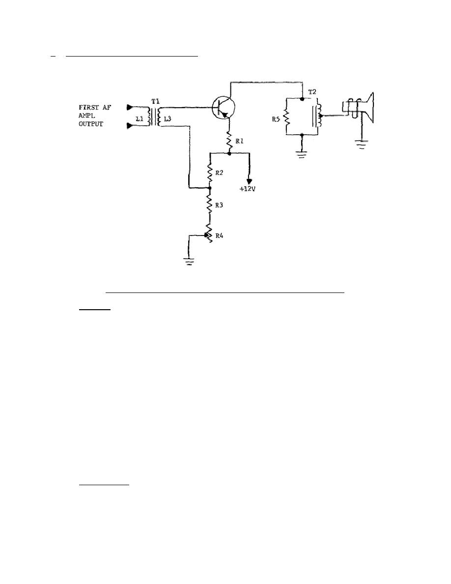
b. Single-Ended AF Output Stage.
A class A single-ended audio-output stage
employing a high-power PNP transistor is shown in figure 4-2.
Figure 4-2.
Single-ended transistor output amplifier.
(1) Biasing.
A common-emitter circuit is used, where the forward bias is
developed across R1 from the +12-volt supply in the R2-R3-R4 voltage-
divider network. The magnitude of the bias and, consequently, the output
signal level are changed by varying R4, the bias-adjust control. Although
this control does affect the output volume, it is not a substitute for a
volume control; a volume control is normally included as part of a
detector circuit.
The primary purpose of R4 is to set the operating
conditions for the transistor to maintain the low-distortion output that
is characteristic of a class A amplifier.
This biasing circuit is a
series-parallel circuit.
The R4 and R3 are in series with the 12-volt
supply and the circuit consisting of R2 in parallel with L3, the base-
emitter junction, and R1. With R4 set at maximum resistance, 12 volts is
dropped across the entire series-parallel circuit and a fixed amount of
current is permitted to flow. If R4 is reduced to minimum resistance, the
total resistance is reduced so that more current will flow for the same
applied voltage.
More current through R1 means a larger difference of
potential between the base and emitter.
This increase in forward bias
results in an increase of collector current.
Resistor R1 stabilizes the
collector current, and prevents a possible runaway condition due to
transistor heating.
(2) Signal path. The input signal is coupled from the audio preamplifier to
the base-emitter circuit, amplified, and then coupled to the loudspeaker
through autotransformer T2. Resistor R5 protects
322 L4
28


 Previous Page
