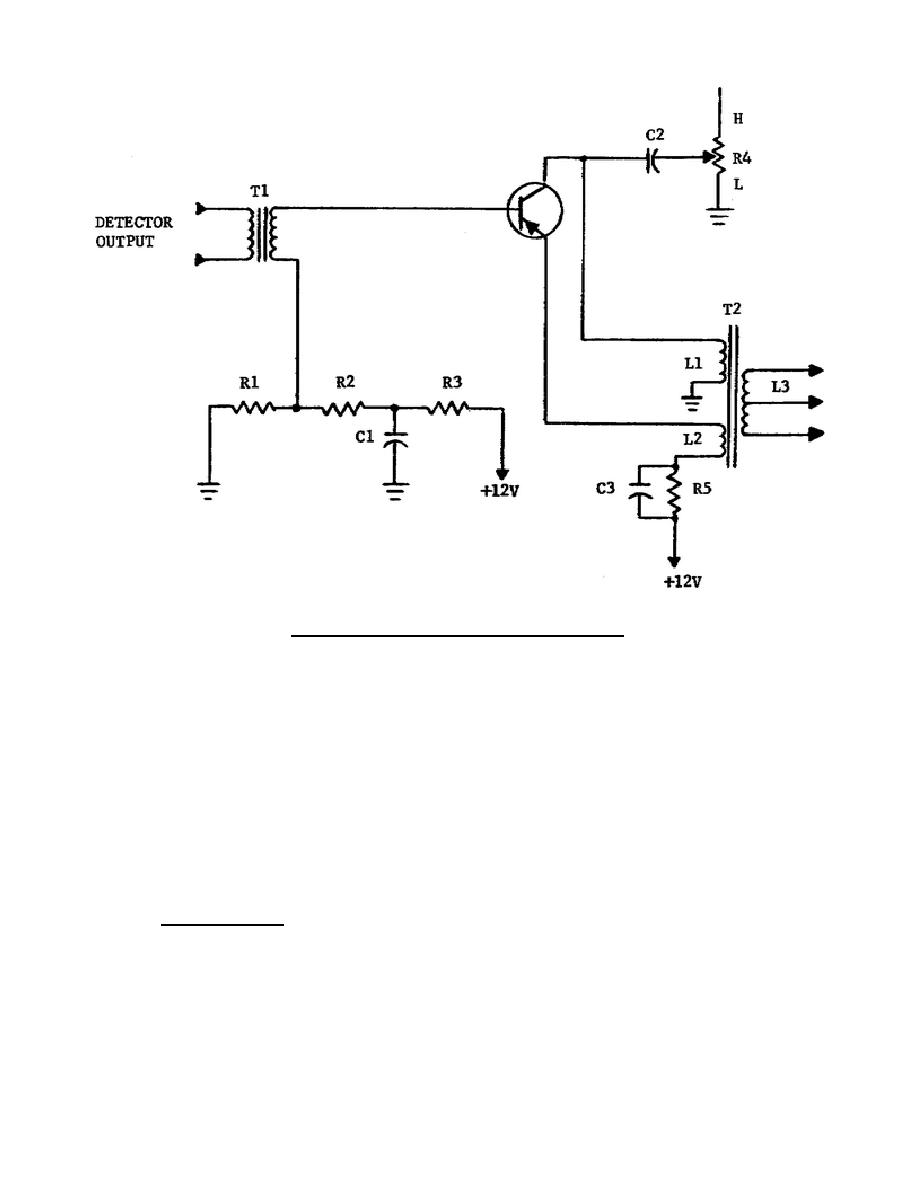
Figure 4-1.
Transistor preamplifier.
a degenerative voltage from developing at this point. The 12-volt source
also connects to the emitter through R5 and winding L2. The collector is
connected in series with primary winding L1 of output transformer T2.
With no signal input, the collector current flows at a constant value.
When the input signal is applied to T1, the collector current varies at
the signal rate.
The output signal appearing across L1 is a replica of
the input signal, but greater in amplitude. The signal voltage is induced
into L3, where it is fed to the audio output stage. The same voltage is
also induced into L2. The voltage across L2 is degenerative and cancels a
portion of the original current appearing in the base-emitter circuit.
This action is desirable because at this point in the circuit the
degenerative signal minimizes distortion by canceling the harmonics which
are generated within the transistor.
Harmonic distortion cannot be
canceled out until it occurs.
(3) Tone control.
Tone control resistor R4 is connected to the collector
through C2.
Functionally, this control changes the amount of resistance
in series with C2 and ground.
The lower the resistance, the more
efficient C2 becomes as a bypass for higher frequencies. With the control
arm at position L, a maximum amount of high-frequency audio is bypassed
and the tone quality is at its lowest. As the control is moved toward H,
more resistance is added and less high-frequency audio is grounded, thus
producing better tone quality.
322 L4
27


 Previous Page
