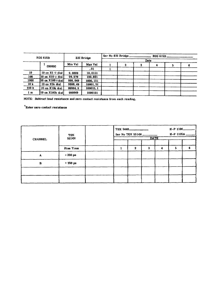
the minimum and maximum deviation allowable. In this case, the resistance
of the decade resistor is measured on the impedance measuring system (ESI
bridge). You can see from table 6 that the decade resistor dials are set
for five different settings and each setting is measured on the ESI bridge.
Table 6.
Tolerances for decade resistor
Table 7.
Tolerances for graphical display system risetime
h. In Table 7 the TEK 5440 oscilloscope acts as a monitor since the
signals are displayed on the CRT.
The H-P 1105A or H-P 1106A is the
external generating source used to cross-check the 5S14N plug-in unit. Note
the dual inputs (A and B).
i. Table 8 shows the equipment required to check the digital counter
timebase.
This table lists the SYA digital counter only, but it must be
understood that this setup can also be used for other digital counters. The
reference signal source for this cross-check is the VLI FS 323 Quartz
Crystal Oscillator as monitored by the VLF receiver and the actual check
made by the HEC FDM 2100 Frequency Difference Meter.
186


 Previous Page
