
MM0704, Lesson 4
To explain the action of saturable transformers, assume there is no load on the secondary. Also, assume the applied
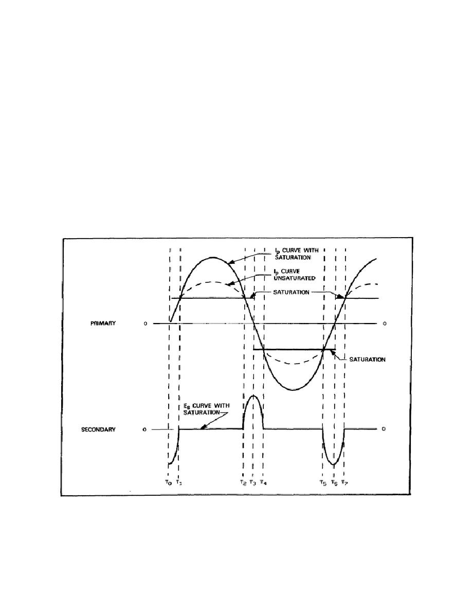
voltage is a higher value than that needed to cause enough current to flow to saturate the core. Figure 4-26 is a graph of
this transformer's operation. At time T0, Ip is at zero and Es is at a maximum negative value, since it lags Ip by 90.
As the primary current starts to build up in a positive direction, Es starts to decrease toward zero. At time T1 on the Ip
curve, the current has reached a value where the core is magnetically saturated. Any further increase in Ip does not
affect the flux, and no voltage is induced in the secondary. At time T1, Es therefore drops to zero. Since the core is
saturated, the inductive reactance of the primary will not prevent Ip from reaching a high value. The dotted line on the
Ip curve represents the normal current flow without saturation.
As long as Ip remains at a value higher than that necessary to saturate the core, the flux produced will remain at a
constant level, and no voltage will be induced in the secondary. This action is shown from T1 to T2. At time T2, Ip
has reached the value necessary to saturate the core and is decreased below that point. Since the flux is again changing,
a voltage is induced in the secondary and Es rises to its positive maximum value at T3. Toward T4, Ip is increasing in
amplitude in the negative direction and, at T4, again produces magnetic saturation in the core. With the flux again
stationary Es
Figure 4-26. Output Waveshape of a Saturable Transformer.
98

 Previous Page
