MM0704, Lesson 4
AUDIO TRANSFORMERS
As yet the effect of frequency on a transformer has not been considered. The rapidly changing polarity of voltage at
frequencies higher than normal power frequencies increases the iron losses due to residual magnetism. This is evident
since the molecular friction, due to the rapidly changing polarity, is increased as the frequency increases.
For transferring energy from one circuit to another at audio frequencies, special transformers use a core material having
a very low degree of retention. At these higher frequencies, residual magnetism left in the core material by the effect of
one-half cycle will cause an undesirable lag in the secondary voltage. Audio frequencies range. Because audio
transformers must transfer this range of frequencies from about 20 to 20,000 Hz from one circuit to another without
distortion, they are very carefully designed. In some cases, the secondary is center tapped, and when it is, great care is
taken to see that the windings contain the same inductance on each side of the center tap.
RADIO FREQUENCY TRANSFORMERS
When working with the radio frequencies (RF) (above the audio range), the iron core transformer used for power and
audio frequencies is no longer practical. The advantage from reducing flux leakage through the use of a suitable core is
offset by the loss due to hysteresis at these frequencies. Many RF transformers have air cores. Some, however, use
special powdered iron cores.
Air core transformers have very little coupling between the primary and secondary, since all the flux emanating from
the primary is not cutting the secondary winding.
You can assume that the coefficient of coupling is so small it is negligible in regard to the effect of secondary load on
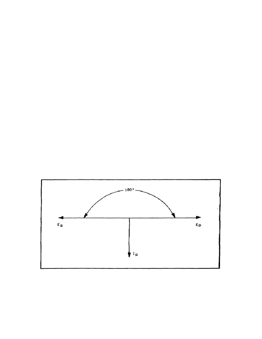
the primary circuit. Vectorially, you can show an air core transformer (figure 4-20) with an unloaded secondary the
same way you plotted the iron core transformer. For practical application, however, the secondary of the air core
transformer is usually loaded with a capacitor
Figure 4-20. Vector Diagram of an Air Core Transformer.
94


 Previous Page
