MM0704, Lesson 4
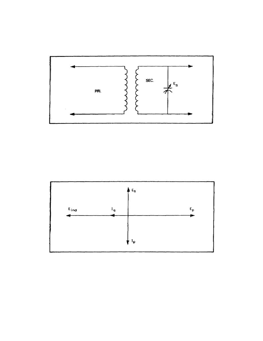
In figure 4-21, the secondary circuit is an LC circuit. You know that L and C is resonant at some frequency determined
by the values of L and C. The secondary winding can be considered a generator. This being the case, the secondary is
actually a series LC circuit. You can assume that the secondary circuit has negligible effect on the primary circuit.
Figure 4-21. Air Core Transformer.
You can see that the primary is a simple inductive circuit in which the current lags the voltage by 90. This is shown in
figure 4-22. You also know that the induced voltage (Eind) lags Ip by 90. To determine lag in the secondary, first
assume that the secondary circuit is tuned to resonate at the frequency of the applied voltage. At resonance, the two
reactances cancel leaving only the resistance of the circuit. Therefore, the secondary current is in phase with the
induced voltage. However, secondary voltage is being obtained across the capacitor; this voltage lags the current by
90. The result is that the secondary voltage (Ec) leads the primary voltage by 90.
Figure 4-22. Vector Diagram for a Tuned Secondary
By leaving the secondary tuned to the same frequency, you can determine what to expect if higher frequency is applied
to the primary (figure 4-23). The Ep, Ip, and Eind vectors are the same. In the secondary however, since the frequency
is higher than the resonant frequency, the circuit acts inductively. This being the case, as you deviate from the
resonance, the Is lags the
95


 Previous Page
