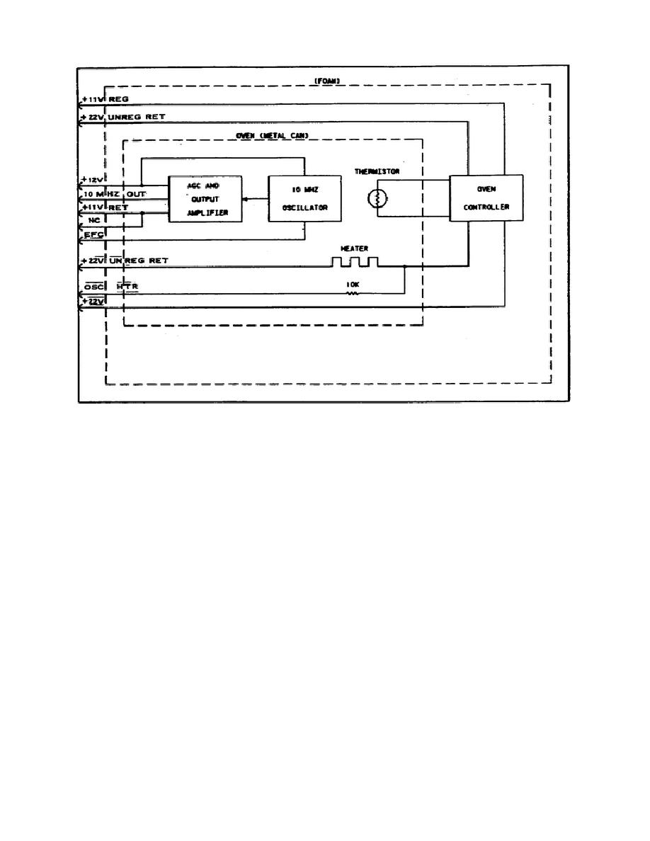
Figure 6.
Oven-controlled crystal oscillator.
Digit Driver Transistors Q10-Q20.
The minus sign is driven by Q9.
The
annunciators are fixed symbols which are backlighted by incandescent lamps.
Cathode driver transistors Q1-Q8 are used to enable the segments for the
decimals, minus sign and decimal points.
The result of a measurement is displayed by using a strobing
technique. That is, only one digit of the displayed number is on at any one
time.
One digit is displayed and then removed; then the next digit is
displayed and removed. This process is continued until all digits have been
shown.
The strobing process occurs at a faster rate then the eye can
detect, so the display appears continuously lit. The 4 line to 7 Segment
Decoder, U6, controls the digit (numeric character) to be displayed, while
the BCD-to-12 Line Decoder (U1) controls the placement of the digit in the
display.
The
BCD
data
lines
carry
the
digit
information
from
the
Adder/Subtracter to the character generator (U6). The BCD lines are decoded
by U6 into segment lines for the LEDs.
Each segment line enables an
individual segment of the LED display.
Each of these segment lines are
connected to the same segment in each digit. The turn-on of these
47


 Previous Page
