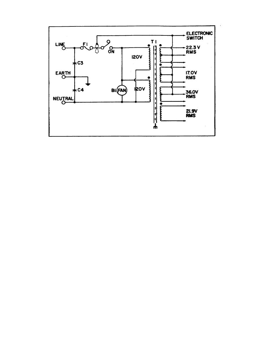
Figure 8.
Power transformer.
Electronic Shutdown circuitry which is identical to that described for the
Switching Regulator.
(a) +12V Oscillator supply.
The 12V, 22V, and 11V supplies
receive power from the 36V rms secondary of R1. CR2 rectifies the ac into
+22V and -22V. The +22V output is unregulated while U2, U1 and U4 regulate
the +12V, +11V, +15V and -15V supplies.
(b) +20V Supply.
Diode assembly CR1 rectifies the 21.9V rms
voltage from T1 secondary into +20V.
U5 regulates the output while CR10
clamps the common terminal to the output in the event of a short to common.
To summarize, the Model 5345A is composed of an Input Assembly which
contains two identical circuits for Channels A and B. There the signal to
be measured is both attenuated and amplified before being applied to the
Schmitt Triggers for pulse conversion.
The Main Gate contains the Input
Selector, Main Gate, Scalers and Turn Off Control. These select the proper
signals for a particular measurement, control the gating of the input signal
and clock signal, and divide the time and event signals by a factor of 10.
50


 Previous Page
