c. The 100-volt pulse continues along the line and arrives at points
(3) and (4). Finally, as shown in Part C of Figure 29, the complete ATL is
charged to 100 volts, twice the voltage originally applied.
13. Determining the time delay.
a. To determine the time it took for the pulse to get from one end of
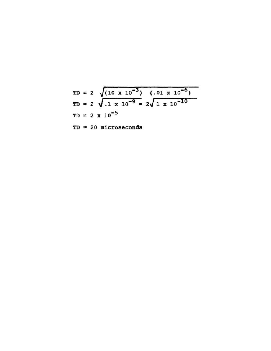
the line to the other, we use the time delay formula, TD = N LC. In this
case, the value of each coil is 10 mh and the value of each capacitor is .01
uf. The ATL has two sections. Calculating, we get:
b. The pulse took exactly 20 microseconds to get from the battery end
of the line to the open end. The values of L, C, and N are the same for the
returning pulse; therefore, it takes 20 microseconds for the reflected pulse
to return.
The complete action takes 40 microseconds.
Thus, the time
required to charge an ATL is equal to twice the delay time of the line
because the voltage has to go to the end of the line and back. The voltage
on the line will remain at 100 volts until the line is discharged.
14. A review of the main points thus far.
a. ATL have the same electrical characteristics as real transmission
lines but take up much less space.
b. ATL are used as pulse-forming networks in radar systems.
c. A pulse takes a definite amount of time to travel from one end of an
ATL to the other.
d. An ATL terminated in an open circuit will charge to the supply
voltage in twice the delay time of the line.
15. Now, let's discharge the ATL.
a. You have just seen how to charge an ATL and that an ATL charges to
the supply voltage in a definite amount of time. It takes two TDs to charge
the ATL when the characteristic resistance of the ATL equals the source
37


 Previous Page
