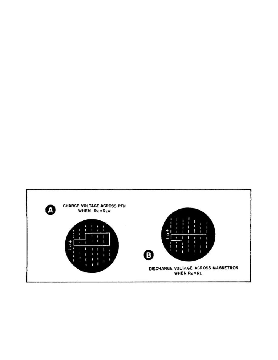
shows that, at the first instant of time, the PFN charges to the supply
voltage. The PFN remains at the supply voltage for a time equal to two TDs.
Then it rises to twice the supply voltage and remains at this potential
until discharged. The figure on the scope is called a two-step waveform.
(2) Part B of Figure 33 shows the waveform across the load as the PFN
discharges.
The discharge current flows in a direction that gives us a
negative voltage across the load. At the first instant of time, the voltage
across the load goes from zero to the supply voltage. The voltage across
the load remains at the supply voltage (negative polarity) for two TDs and
then goes to zero again. Thus, we have a negative pulse that has a width
equal to twice the delay time of the PFN. This pulse causes the magnetron
to oscillate at the radar carrier frequency.
(3) In this circuit, we assumed that in the PFN, Rc equals RL. This
is the ideal condition and desired for the PFNs you will be using. These
are some important circuit characteristics in this case.
(a) A PFN produces a two-step waveform only when the PFN charges
through a resistance equal to the characteristic resistance of the network.
(b) When a PFN is discharged through a resistance equal to the
characteristic resistance of the network, a rectangular pulse is formed.
(c) The amplitude of the pulse is equal to one-half the voltage to
which the line is charged.
(d) The pulse width is equal to two TDs.
Figure 33. Waveforms of PFN.
41


 Previous Page
