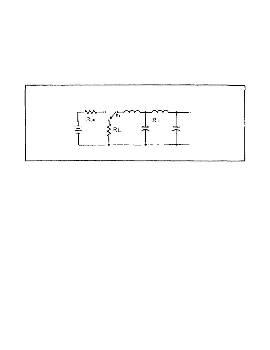
b. Now, if we connect a resistor (or some other component) across the
ATL, it provides a discharge path. In a radar set, the main purpose of the
ATL pulse-forming network is to discharge through the magnetron. When the
ATL pulse-forming network discharges through the magnetron, the magnetron
generates the radar RF carrier.
c. The characteristic resistance RC of the charged ATL is equal to the
source resistance Rch. We will discharge the ATL through a load resistor RL
that has a resistance equal to both RC and Rch.
In Figure 30, switch S1
disconnects the battery and connects the discharge path RL across the ATL.
Figure 30.
Discharge Path Connected to ATL.
d. Rc and RL are equal.
So, the 100-volt charge divides equally,
placing 50 volts across Rc and 50 volts across RL. This means that the 100-
volt charge across the ATL goes in a negative direction, dropping from 100
volts to 50 volts. The negative-going 50 volts travels along the line and
is reflected in the same polarity (negative direction) and amplitude. The
negative-going 50 volts travels along the line and is reflected in the same
polarity (negative direction) and amplitude.
The incident and reflected
voltages add (-50 volts and +50 volts) and the voltage across the line drops
to zero.
Part A of Figure 31 shows that the voltage across the ATL (Rc)
drops to 50 volts for two TDs and then drops to zero.
e. Part B of Figure 31 shows the pulse across the load resistor (RL).
The instant switch 51 is closed; the voltage across RL rises to 50 volts.
It remains at 50 volts for two TDs and then drops to zero.
38


 Previous Page
