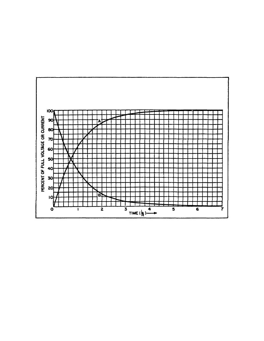
instantaneous values of the voltage across the resistor are directly
proportional to the current flowing through it, the ER curve is
identical to the It curve. The inductor voltage is represented by
Curve B in Figure 18. If the polarity of the EL curve is reversed,
it may be considered to represent the counter emfin the inductor.
(The polarity of the counter emf is always opposite to that of the
applied voltage.)
Figure 18. Universal time constant chart for series
RL circuit
c. Theoretically, the current never stops increasing, because it
never reaches 100 percent of its maximum value. In actual practice,
when the current is equal to approximately 99.9 percent of its
maximum value, it is considered to be equal to the maximum value and
EL is considered to be equal to zero.
4.
NEGATIVE STEP VOLTAGE.
a. When the negative step voltage is applied to the series RL
circuit, E (Figure 17B) drops instantly to zero. The magnetic field
about the inductor collapses, and in the process, induces a
37


 Previous Page
