c. After 70 usec, 7 time constants have elapsed. EL is then
equal to zero, and ER and It are equal to 100 percent of their
maximum value or 1 volt and 1 mA, respectively. The current and
voltages of any series RL circuit can be determined by substituting
the appropriate values of E, R, and L.
8.
STEPBYSTEP PROCEDURE FOR DETERMINING TRANSIENT RESPONSE.
a. When a universal time constant chart is not available, the
response curve can be approximated by using the equation for finding
the rate of change of current through an inductor. This equation
states that the rate of current change is equal to the instantaneous
voltage EL, divided by the inductance L. The following stepbystep
procedure can be used to provide an approximate response of an RL
circuit to any waveform.
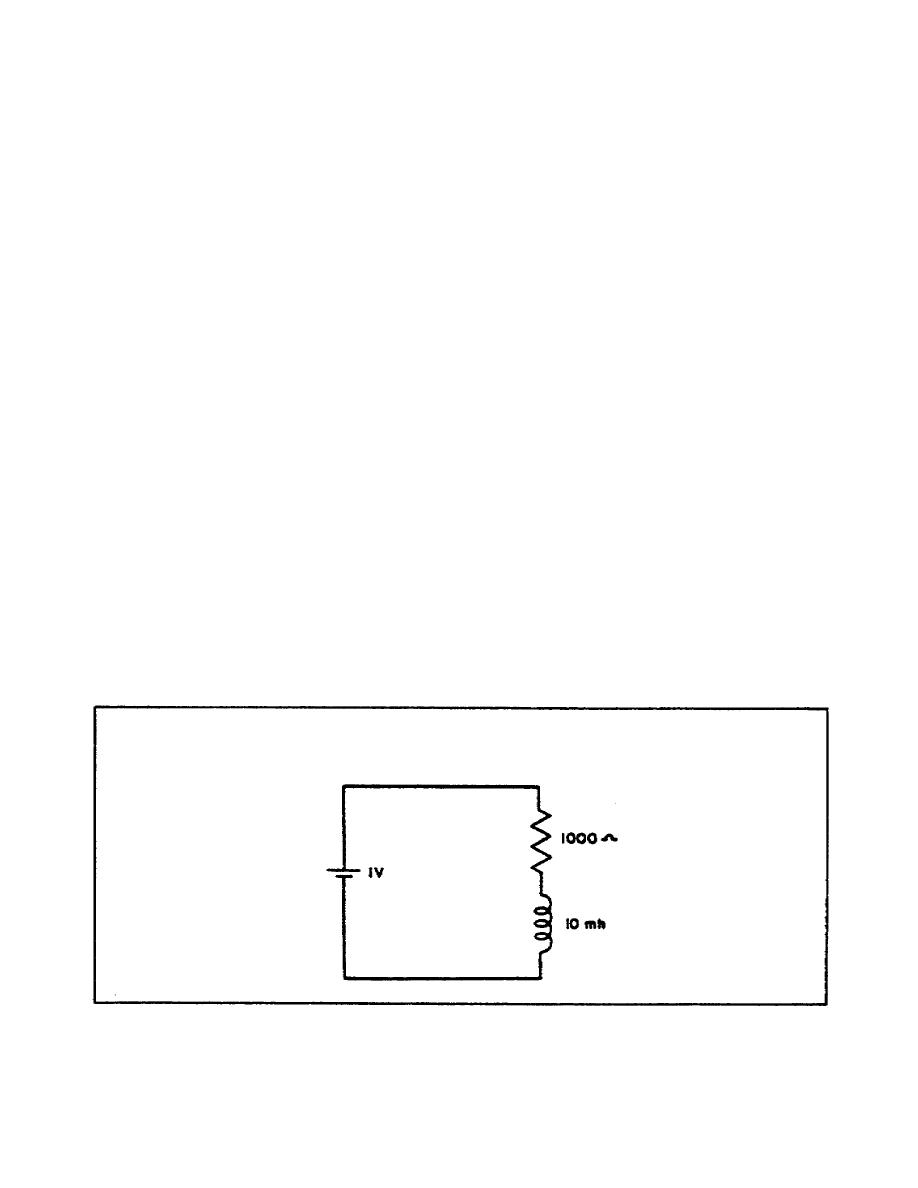
b. In this procedure, it is assumed the current does not increase
continuously, but in small steps. At the instant that the voltage in
Figure 19 is applied to the circuit, the current is zero and the
applied voltage appears across L. The initial rate of current
increase is equal to EL/L or 1/10 x 103, which is equal to 100
amperes per second, or 0.1 mA per usec. After 1 usec, the current is
considered to have increased from zero to 0.1 mA. With a current of
0.1 mA flowing in the circuit, ER = 0.1 x 103 x 103 or 0.1 volt. EL
then equals 0.9 volts and the rate of current change is reduced to
0.9/10 x 103 or 0.09 mA per usec. The current still is increasing,
and at the end of 2 usec, it becomes 0.1 + 0.09 = 0.19 mA.
Figure 19. Series RL circuit
41


 Previous Page
