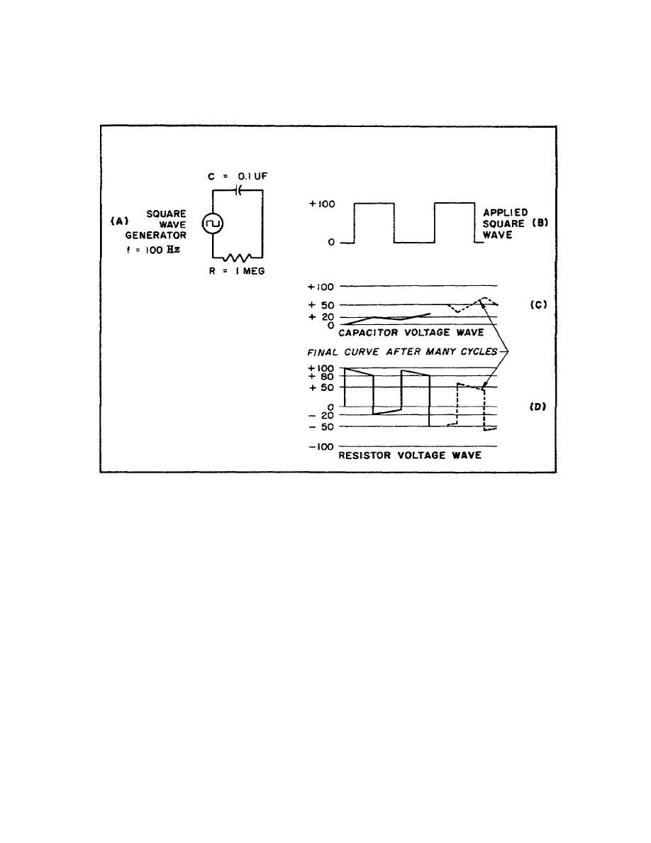
above and below the zero voltage axis. The waveforms for Ec and ER,
at this time, are illustrated by the dotted lines in Figures 26C and
26D.
Figure 26. Waveshapes for longtime constant RC circuit
c. Response of RL circuit.
(1) In a series RL circuit, the current and, therefore, the
resistor voltage varies in exactly the same manner as the capacitor
voltage in a series RC circuit. The inductor voltage waveform is the
same as the current and resistor voltage waveforms in an RC circuit.
In Figure 27A, a square wave is applied to an RL circuit in which the
time constant is equal to onehalf the duration of one complete cycle
(duration time). At the first instant the square wave is applied, a
back emf equal to E is developed across the inductor, and no current
flows. Current then begins to flow in the circuit at a rate
determined by the universal time constant chart (Figure 18). At the
end of 1 time constant, the current (Figure 27C) has increased to
approximately 63 percent of its steadystate value E/R. The voltage
across the resistor, therefore, is equal to approximately 63 percent
of E applied (Figure 27E), and EL has decreased to approximately 37
percent of
55


 Previous Page
