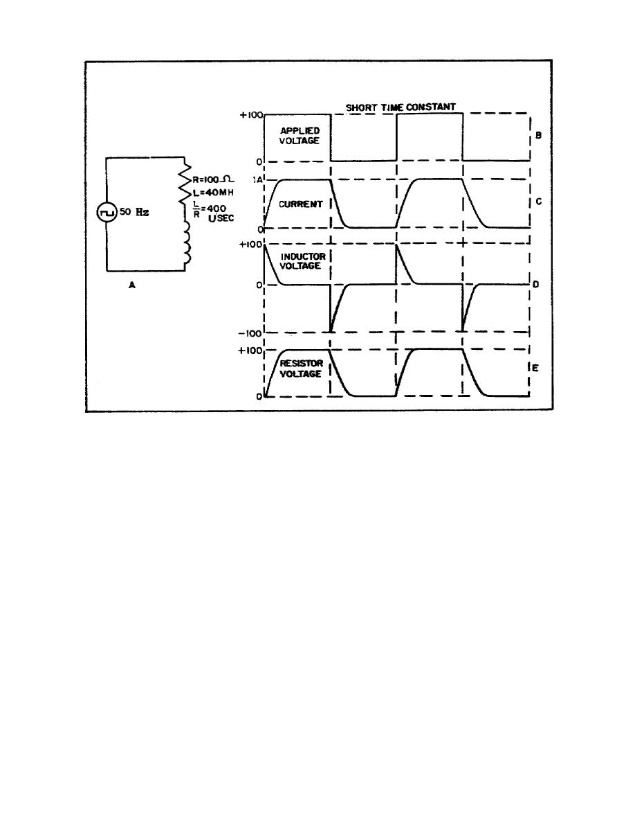
Figure 28. Effect of short RL time constant
(3) The waveshapes illustrated in Figure 29 are those produced
when a square wave is applied to an RL circuit having a longtime
constant in respect to its duration time. The time constant used in
this circuit is 10 times the period of one complete input cycle, or
20 times the duration time. Since each halfcycle represents only 5
percent of 1 time constant, the current, resistor voltage (Figure
29D), and the inductor voltage (Figure 29C) changes are practically
linear. The resistor voltage starts each cycle at a slightly higher
value, and the inductor voltage starts at a slightly lower value,
until a point is reached where ER varies equally above and below the
average value of the applied voltage, and EL varies equally above and
below zero. These waveforms are illustrated by the dotted lines in
Figure 29.
58


 Previous Page
