
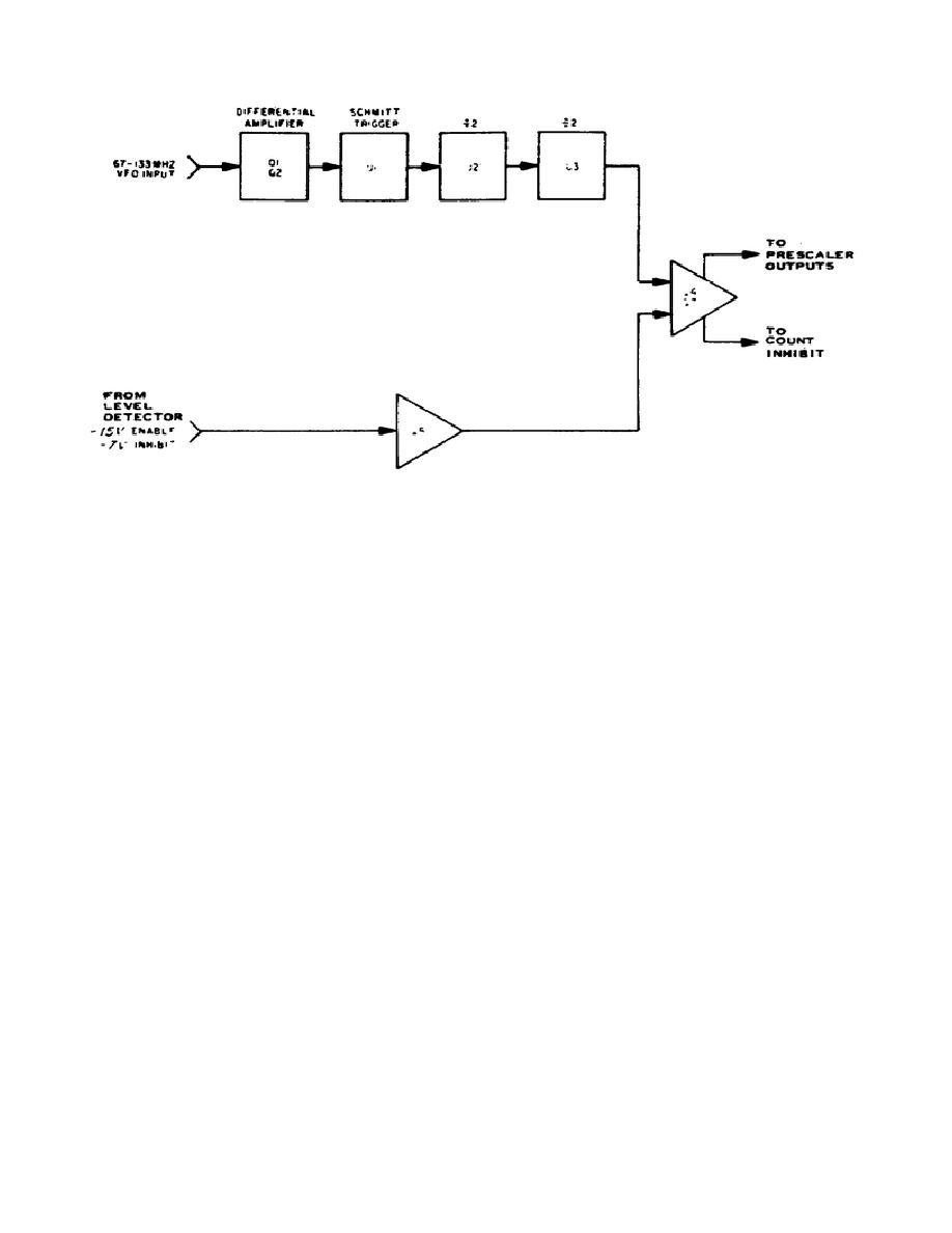
Figure 12.
Prescaler and inhibit.
low on the collector of Q6 sets IC1 and IC4 which prevents the counters from
counting.
Pin 1 of IC3A is high as the input of the holdoff line goes low
(counting). The output from Q6 (inverted) is high, releasing the set of IC1
and IC4. On the next period input to Q4, the plug-in adapter will not clock
IC1, but will enable IC3A to change states. The output of IC3A (pin 6) goes
low and Q9 generates a start pulse.
The counters start counting.
The
output of IC4 (pin 12) will generate a pulse to the preset decades for every
4 period input signals when the counts into the preset decade corresponding
to the thumbwheel settings have been met. A coincidence pulse is generated
putting a high at IC2D (pin 8) turning on Q10 which sends a stop pulse to
cause the N counters to stop counting.
PNP transistor Q8 is driven at its base with a negative spike from the
counter. The base voltage is unclamped from the +4 volt supply by CR3 and
gives an output pulse. The output pulse goes to the thumbwheel switches to
reset the preset decade assembly at the end of sampling time.
(11) N Switch and Preset Decade. Three sets of decade (divide by ten)
dividers are contained in this assembly; one for each of the thumbwheels,
units, tens and hundreds.
Figure 14 shows one of the dividers and its
interconnection to the thumbwheel switch.
This decade divider is an
arrangement of four binary IC flip-flops which give an output pulse for
every ten input pulses. The divider is preset by the thumbwheel switches to
give a coincident output when it reaches a selected number.
76

 Previous Page
