Home
Download PDF
Order CD-ROM
Order in Print
Home
>
Munitions Reference and Training Manuals
>
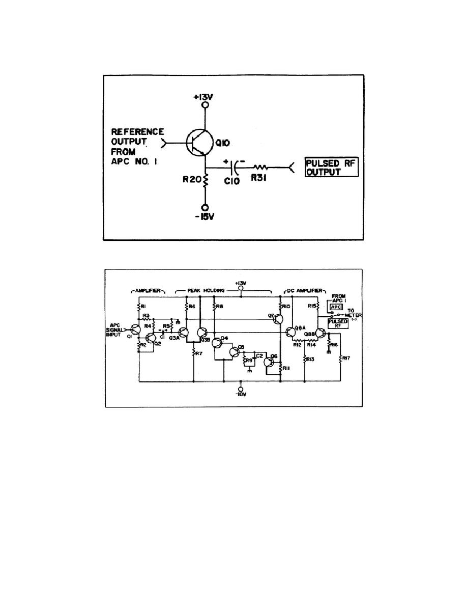
> Figure 8. Pulsed RF output.
Figure 7. Simplified regulator circuit
Figure 10. Automatic phase control no. 2.
Model 5345A Frequency Time Measurment System
Page Navigation
65
66
67
68
69
70
71
72
73
74
75
voltage
starts going negative.
This turns on
Q8B,
allows current to flow
through R15, and the meter deflects.
Figure 8.
Pulsed RF output.
Figure 9.
Peak holding and dc amplifier.
72


 Previous Page
