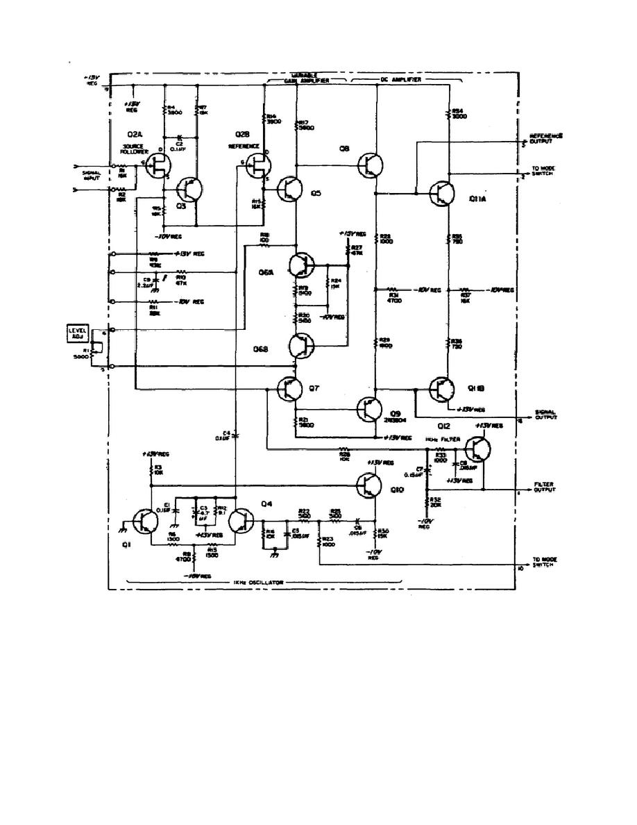
Figure 6.
Automatic phase control no. 1.
(5) Regulator and Pulsed RF Output. The power supplies necessary to
operate the transfer oscillator are obtained from the counter through the
plug-in adapter.
The regulator assembly in the Model 5257A (figure 7)
provides regulated outputs of +13V and -10V.
70


 Previous Page
